Electrics
Electrics
Advanced Electrical Layout
HELIOS 3D simplifies the complex task of electrical layout in solar projects, crucial for efficiency and profitability.
It offers both automatic and manual tools for managing solar tables and string configurations, along with critical calculations like voltage drop and power loss.
HELIOS 3D provides more than data; it offers insights to enhance project efficiency with a digital twin of your electrical layout.
Key Electrical Features
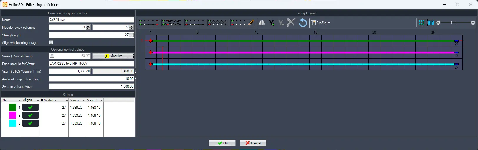
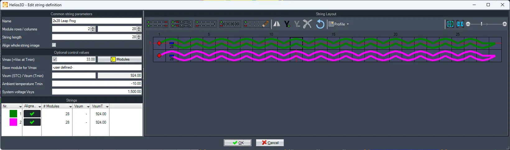
Customize string configurations within system voltage limits for optimal efficiency.
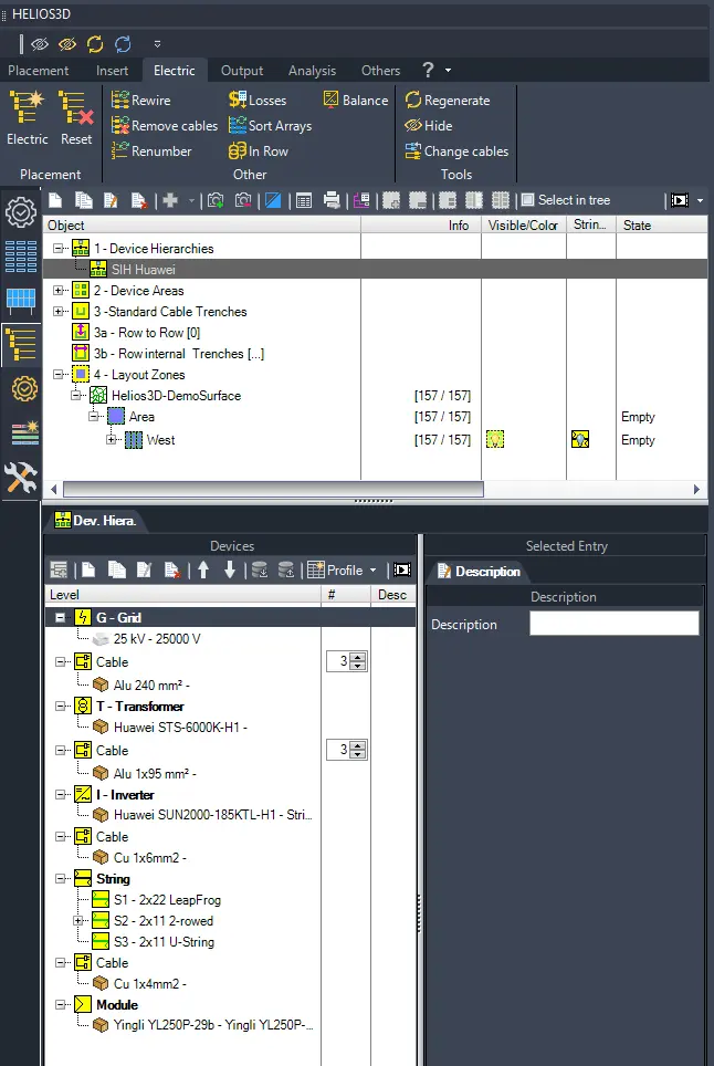
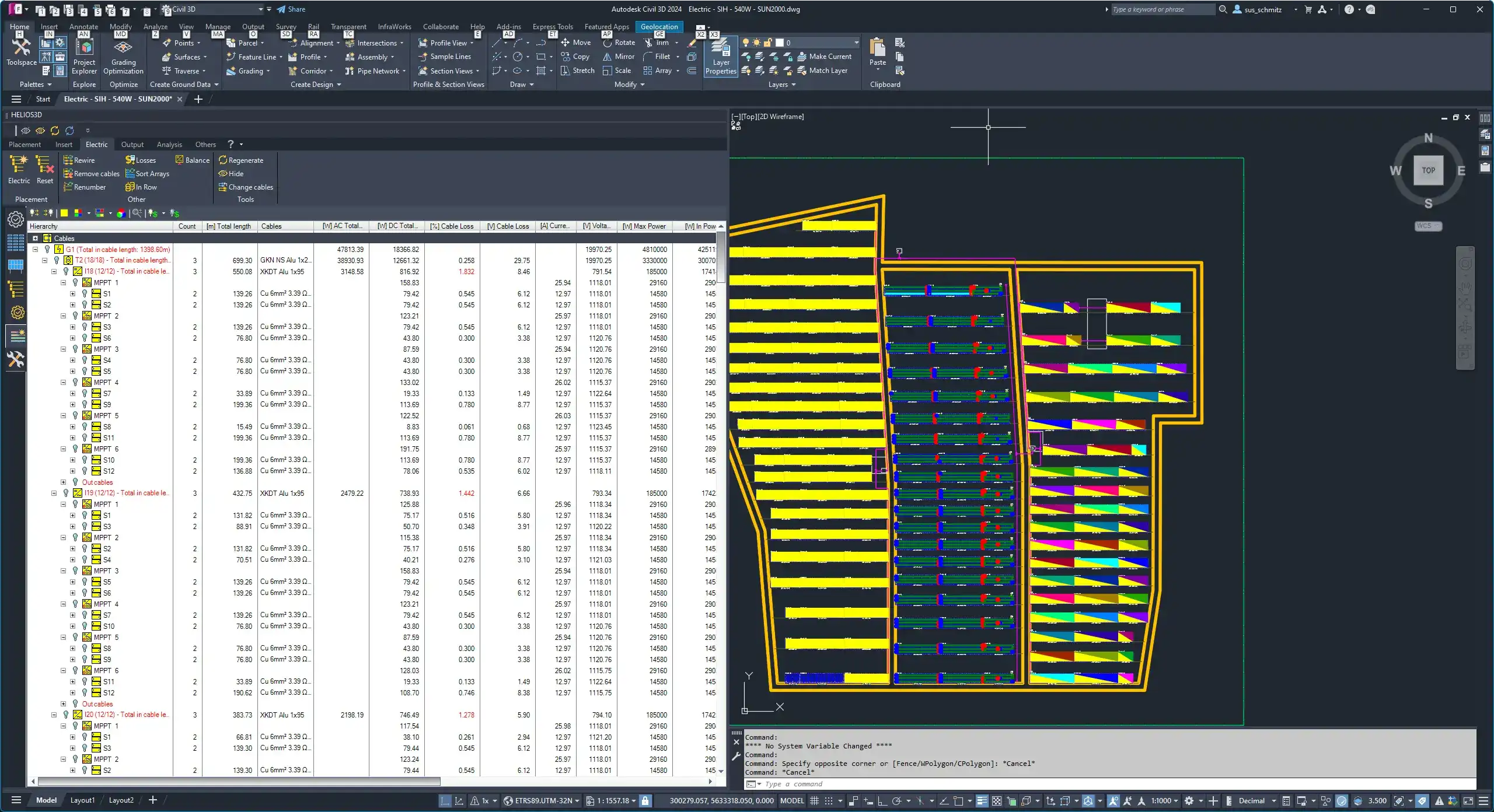
Organize components into a structured electrical hierarchy, defining the electrical structure and assigning physical components.
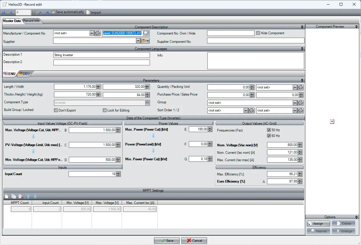
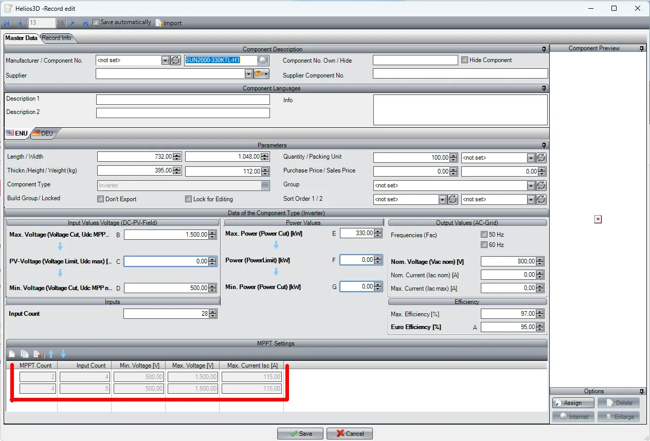
Device Definitions: Specify technical details of each device for accurate simulation and yield estimation.
Specify technical details of each device for accurate simulation and yield estimation.
Manage layouts with inverters having multiple MPPTs, optimizing power output in shaded conditions.
Group related devices like inverters for streamlined management in large-scale installations.
Facilitate parallel connections of solar strings for versatile design options.
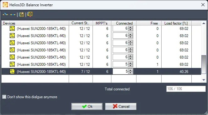
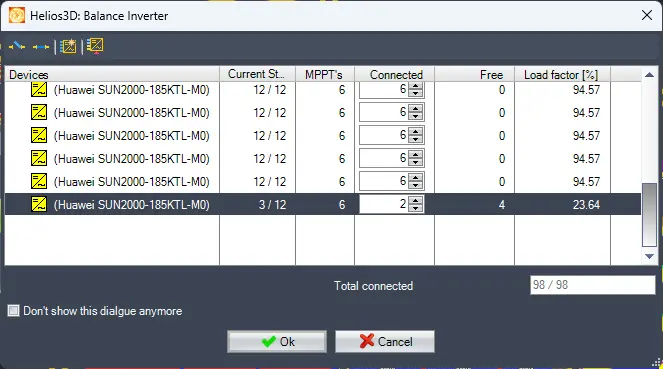
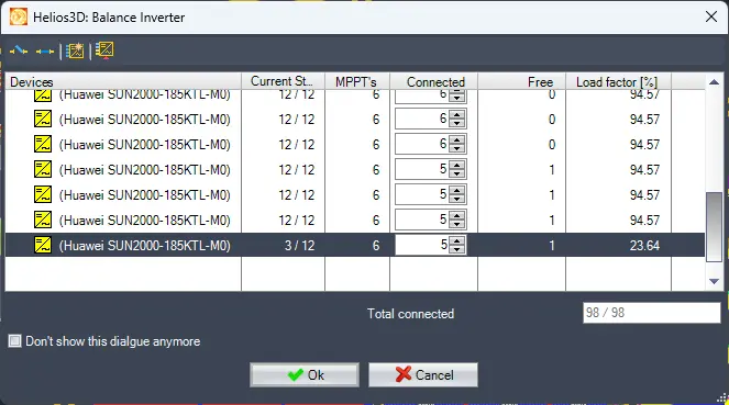
Balance input across inverters and load across multiple inverters for optimal efficiency.
Automatically adjust cables to maintain efficiency and reduce power loss.
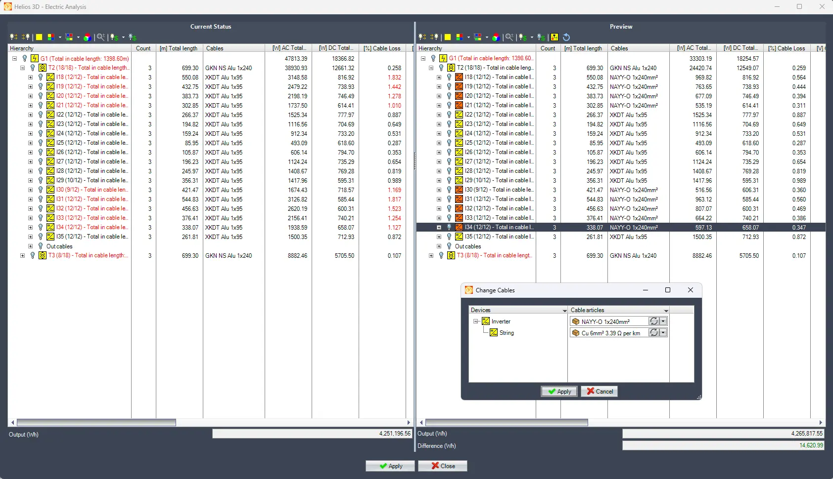
HELIOS 3D computes critical electrical parameters for both AC and DC systems, including cable length, voltage drop, power loss, device-specific power loss, and overall system efficiency. This detailed analysis ensures optimal performance and reliability of solar power systems.
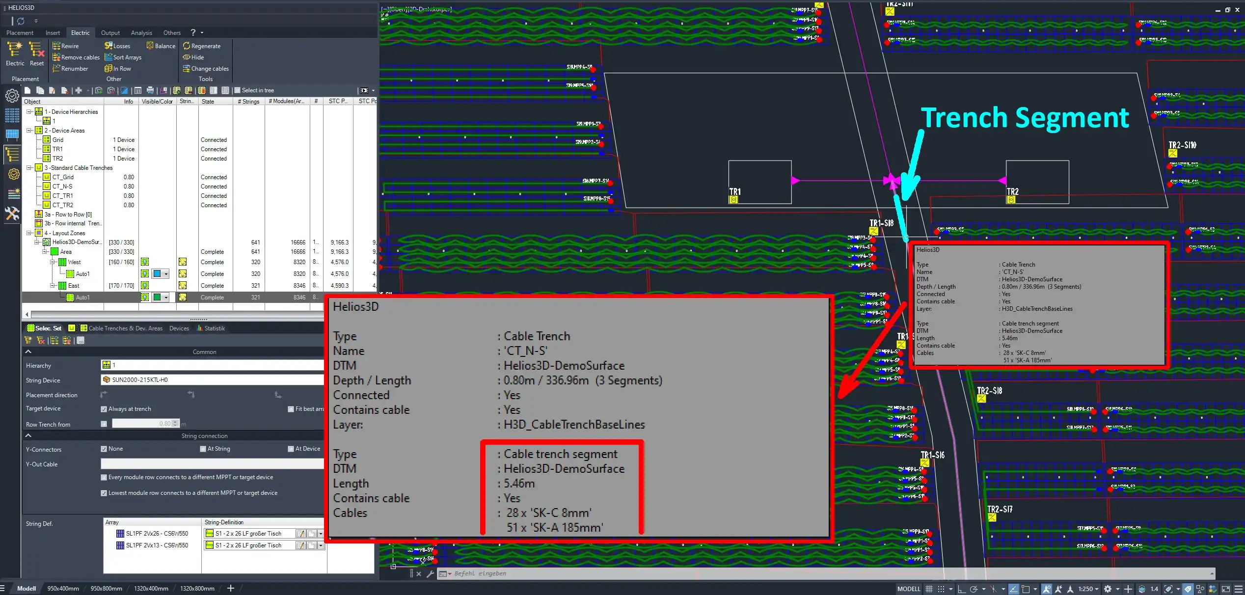
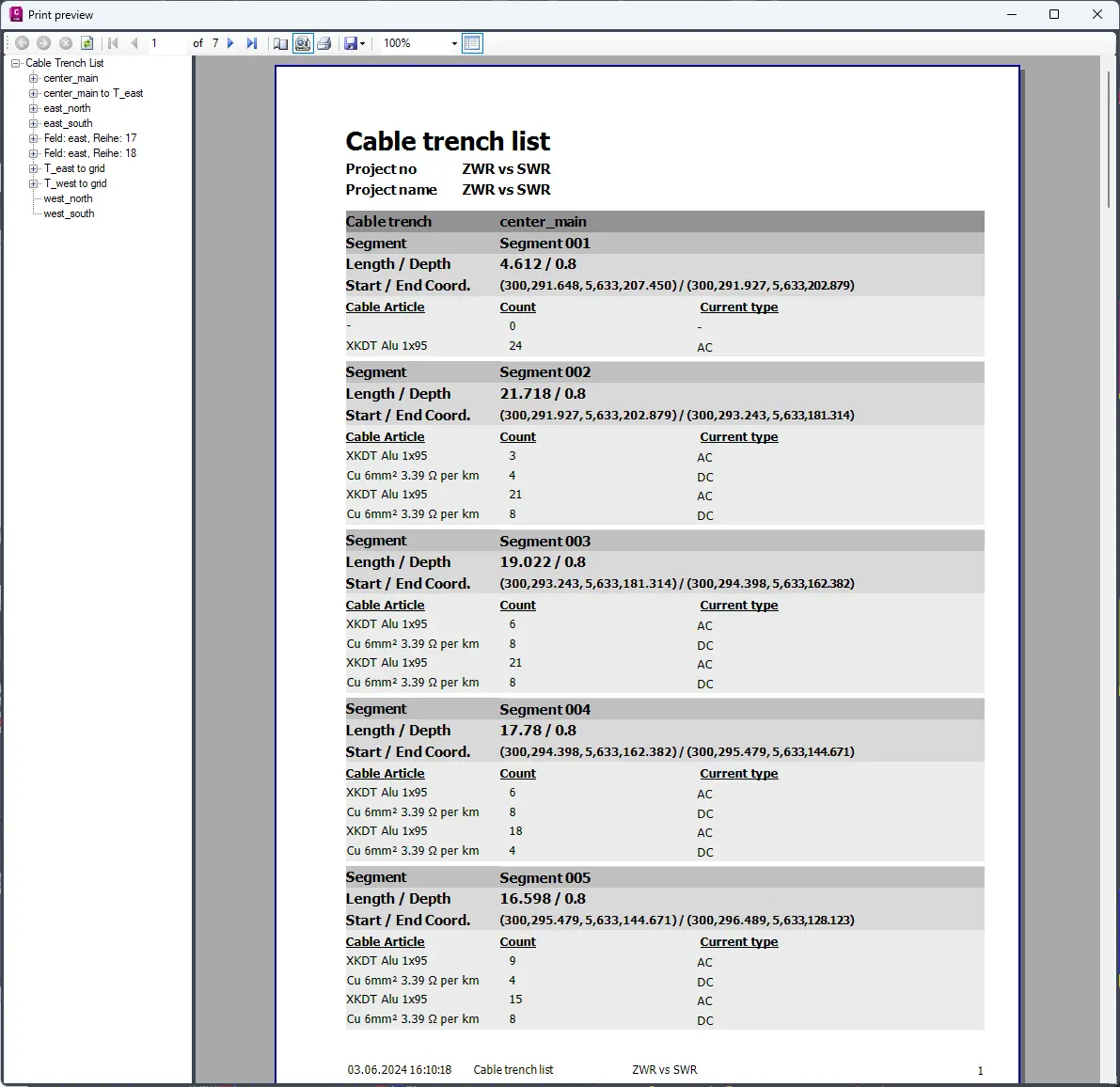
Evaluate cable trench segments for capacity, ensuring safe and efficient cable management.
This mobile-friendly version highlights HELIOS 3D's electrical layout capabilities, ensuring users can quickly understand the software's advanced tools and features for efficient solar project management.
General information
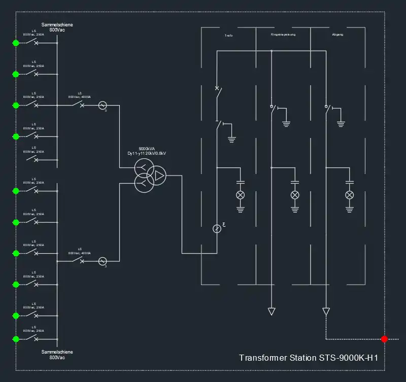
HELIOS 3D has now functions to create single-line diagrams. This simplifies the work and requires a completed electrical layout. The SLD is created from the electrical tree generated by the electrical layout and its level of detail can be controlled by the user. The representation is not based on specific international or national standards. If this should be necessary for the symbols, they can be adapted accordingly by the user. The diagram uses HELIOS symbols for automatic creation. With additional help functions and the description of the HELIOS symbol system, the user can supplement the symbol library with their own, company-specific, more complex symbols. They can then be inserted interactively.
SLD philosophy HELIOS 3D
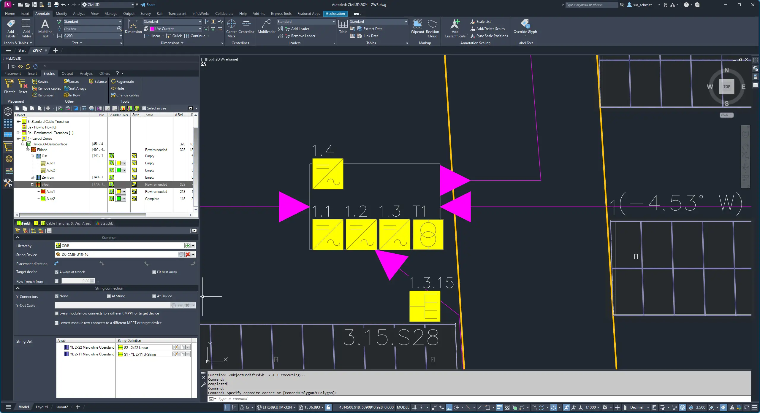
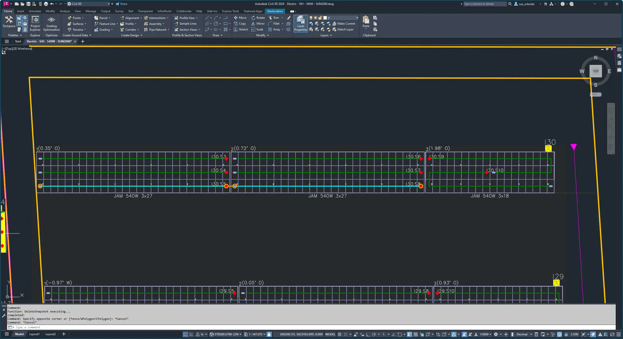
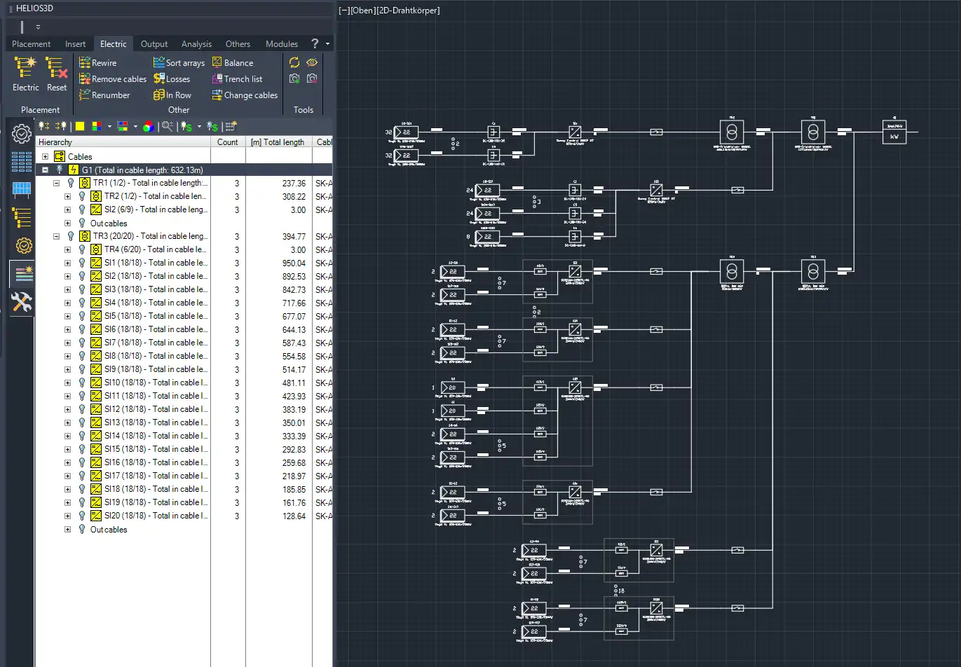
The HELIOS 3D SLDs are generated based on the electrical structure created with the electrical system. The SLD is a direct representation of the electrical tree. At the same time, the electrical tree serves as a preview of what the function should draw. Depending on which parts of the electrical tree are expanded, and which details are visible, the SLD is drawn accordingly.
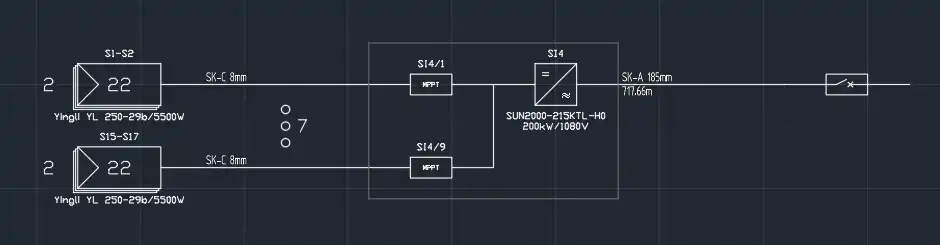
The SLD displays the information from the electrical tree and uses data from the device database to supplement the SLD. Identical elements can be summarised and thus the display height can be shortened. If more than 3 identical structures are found, they are summarised and thus shortened. Here are for example a total of 9 identical elements and 7 have been summarised.
Basics
The function uses predefined symbols for the parts used directly by HELIOS 3D. The H3D-SLD directory contains the HELIOS SLD symbols and can be extended with your own SLD blocks. However, these are not inserted by HELIOS, but by the user.
Customised symbols
HELIOS generates a HELIOS-specific SLD with its own symbols. Many users have their own function blocks in their layouts, which are not available in HELIOS. However, the user can create any complex symbols and use them to manually supplement or change the HELIOS SLD. If they adhere to the HELIOS layer structure and system described above when creating them, they can use some elegant auxiliary functions that are planned for the future.
These include line functions to make it easier to connect elements with each other and the automatic redrawing of certain connecting lines when objects are moved.
Example of a user symbol
The operating menu
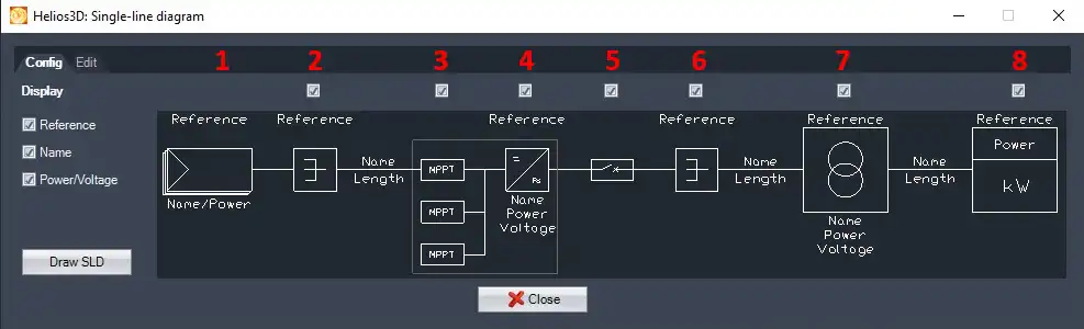
Config
The operating menu has 2 tabs for the operating functions (Config and Edit). The SLD elements found in the electrical structure are displayed in the Config tab and can be shown/hidden/drawn as required. This allows the detailing of the SLD to be controlled intuitively.
Creating partial extracts of an SLD
It is possible to create only parts of an SLD. To do this, select the entry in the electrical tree from which the subordinate parts are to be drawn. Here too, what is visible in the tree is drawn.
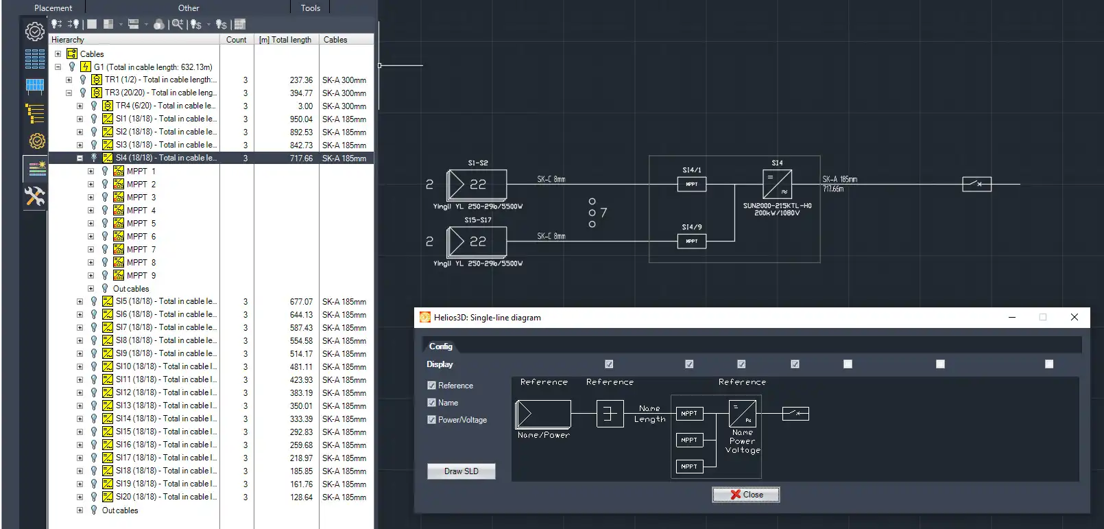
The selected part is drawn with Draw SLD or can simply be dragged and dropped. The SLD is only drawn up to the level that was selected.
Edit
The Edit tab contains functions and help tools for several areas, including functions that make it easy to create symbols in the HELIOS 3D symbol systematic. This makes it much easier to create the layers and elements required for a HELIOS-compatible symbol.
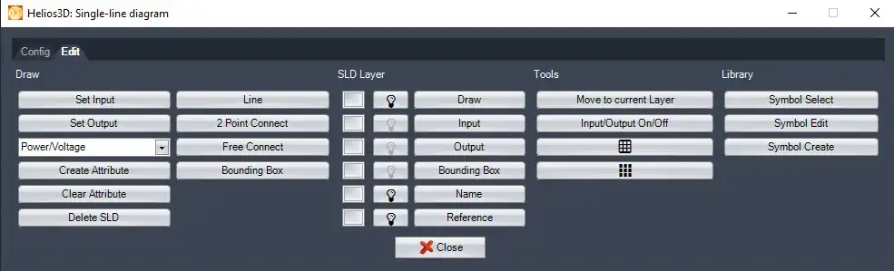
There are 4 categories of functions for drawing, layer management interactive tools and library management. They help in extending the SLD library with own symbols and make them HELIOS compliant.